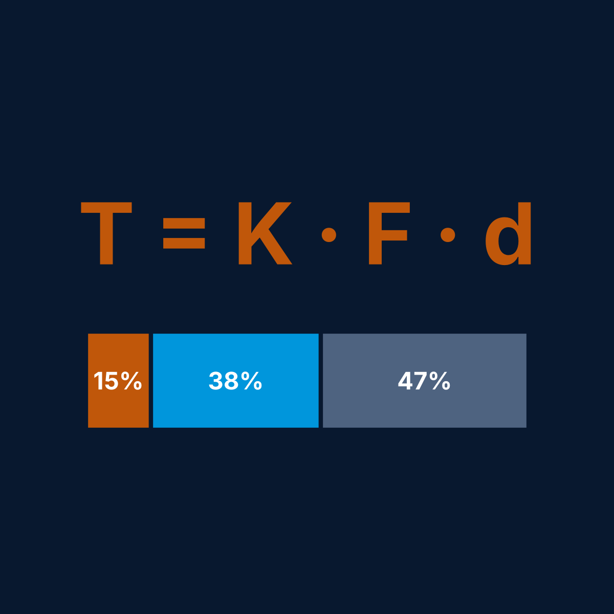
A bolt holds a joint together by clamping it. The clamping force is the preload: the tension the bolt carries after it has been tightened. Torque is only the way most people try to get there, and it is not a very accurate one. Most of the torque you put into a bolt is lost in friction, so the same torque can give very different preloads depending on the finish and the lubricant.
This article explains how to go from the preload a joint needs to the torque you write on the drawing. It covers the simple formula T = K·F·d and the more complete VDI 2230 method that most published torque charts use. It also gives a metric torque chart for property classes 8.8, 10.9 and 12.9 and lists the mistakes that most often lead to loose or broken bolts.
Quick answer: tightening torque T = K × F × d, where F is the target preload, d the nominal bolt diameter and K the nut factor: 0.20 for zinc-plated bolts or an unknown condition, 0.18 lubricated, 0.30 black finish (Shigley). Example: an M10 class 8.8 bolt at 75 % of proof load (25.3 kN) needs T = 0.20 × 25 275 N × 0.010 m ≈ 51 N·m. Lower friction needs lower torque. From the VDI 2230 chart below (μ = 0.12, 90 % yield utilisation), an M10 bolt needs 48 N·m in class 8.8, 71 N·m in 10.9 and 83 N·m in 12.9.
Jump to the metric bolt torque chart, or calculate your own bolt with the free bolt torque calculator on proxom.co.uk.
Why preload matters more than torque
When you tighten a bolt, it stretches like a stiff spring and the parts between the head and the nut are squeezed. As long as the joint stays closed, an external load that tries to pull the parts apart mostly reduces the clamping force between them; only a fraction of it reaches the bolt. With a joint stiffness ratio C (the share of the external load the bolt takes):
- bolt force: Fb = Fi + C·FA
- clamping force on the parts: Fm = Fi − (1 − C)·FA
- C = kb / (kb + km), where kb is the stiffness of the bolt and km the stiffness of the clamped parts
Here Fi is the preload and FA the external tensile load applied to the joint, per bolt (the bolt itself sees only C·FA of it). This simple model assumes the load is applied under the bolt head and nut; VDI 2230 refines it with a load introduction factor n, which usually makes the bolt's share smaller. These relations hold while Fm stays above zero. Because the clamped parts are usually much stiffer than the bolt, C is small, so a well-preloaded bolt sees only a small part of a fluctuating load. That is why correct preload is the most effective way to prevent fatigue failures, joint separation, slipping and self-loosening.
Too little preload lets the joint open or slip. Too much preload yields or breaks the bolt, strips the thread or crushes the clamped parts. The job of the tightening torque is to land the preload between those limits.
Where the torque goes
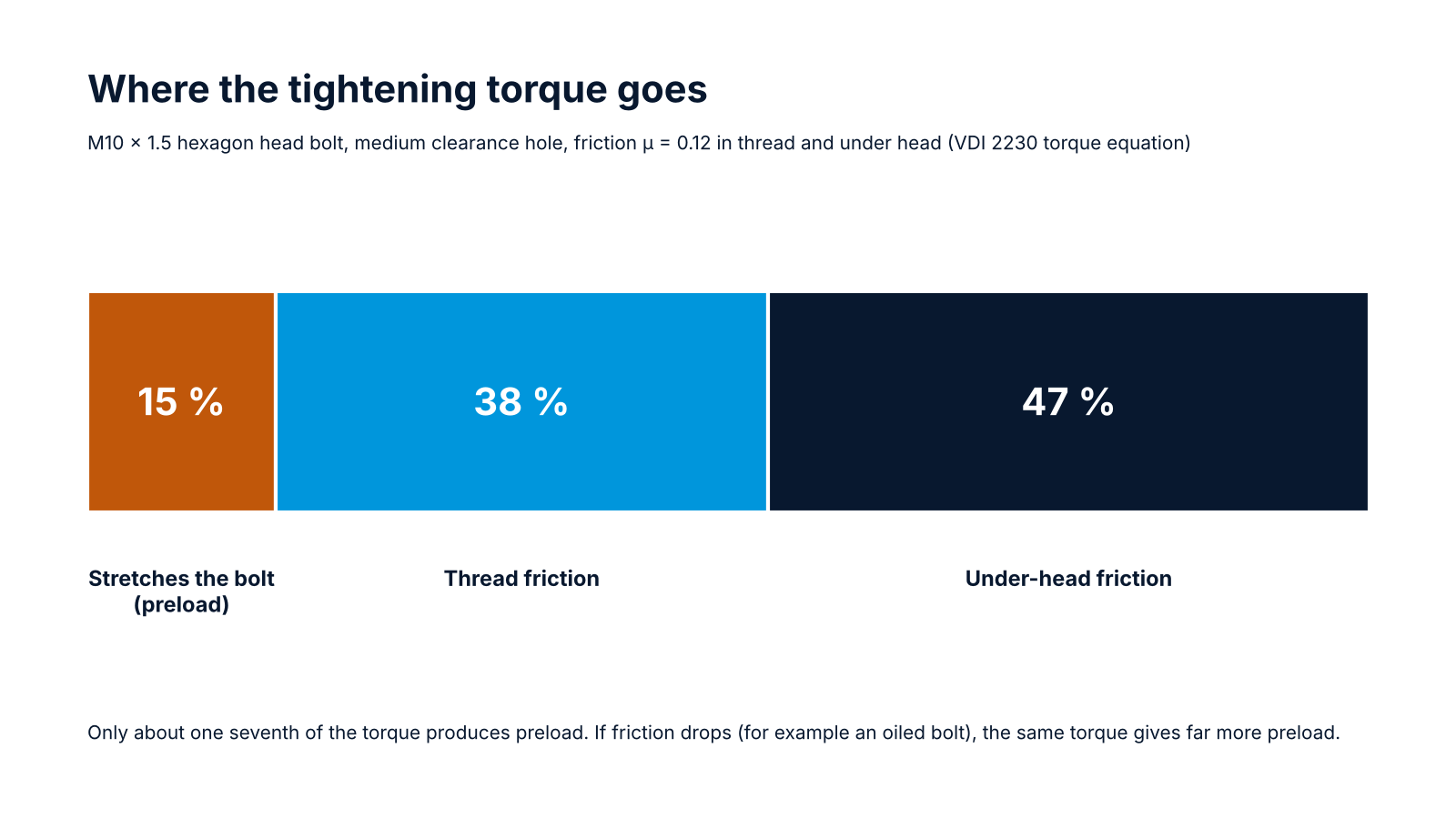
The torque applied to a bolt or nut does three things: part of it stretches the bolt (through the thread pitch), part overcomes friction in the thread, and part overcomes friction under the head or nut. With the VDI 2230 torque equation (shown later), an M10 × 1.5 bolt with a hexagon head in a medium clearance hole and a friction coefficient of 0.12 in the thread and under the head splits the torque like this:
| Share of tightening torque (M10, μ = 0.12) | % |
|---|---|
| Stretches the bolt (produces preload) | 14.7 |
| Friction in the thread | 38.4 |
| Friction under the head or nut | 47.0 |
Only about one seventh of the torque produces preload. So if friction falls, for example because the bolt is oiled, much more of the same torque goes into stretching the bolt. This is the single most important fact about torque tightening.
Step 1: calculate the preload from the proof load
Start from the bolt's proof load: the tensile load that ISO 898-1 requires a bolt to carry without taking a permanent set. It is the tensile stress area multiplied by the proof stress of the property class. The table gives the values from ISO 898-1 (Table 5) for metric coarse threads.
| Thread | Stress area As (mm²) | Proof load 8.8 (kN) | Proof load 10.9 (kN) | Proof load 12.9 (kN) |
|---|---|---|---|---|
| M6 | 20.1 | 11.6 | 16.7 | 19.5 |
| M8 | 36.6 | 21.2 | 30.4 | 35.5 |
| M10 | 58.0 | 33.7 | 48.1 | 56.3 |
| M12 | 84.3 | 48.9 | 70.0 | 81.8 |
| M14 | 115 | 66.7 | 95.5 | 112 |
| M16 | 157 | 91.0 | 130 | 152 |
| M18 | 192 | 115 | 159 | 186 |
| M20 | 245 | 147 | 203 | 238 |
The property class tells you the strength. In "8.8", the first number is one hundredth of the nominal tensile strength in MPa (800 MPa) and the second is ten times the ratio of nominal yield strength to nominal tensile strength (0.8, so 640 MPa). The proof stress used for the table is 580 MPa for class 8.8 up to M16 and 600 MPa above M16, 830 MPa for 10.9 and 970 MPa for 12.9.
A widely used rule from Shigley's Mechanical Engineering Design is:
- Fi = 0.75 × proof load for joints that will be taken apart and the bolts reused;
- Fi = 0.90 × proof load for permanent joints.
Many company standards and the VDI 2230 tables use a different target, as explained below. Whatever rule you use, check that the preload gives enough clamping force for the job (to stop slipping or separation) after allowing for the scatter of your tightening method. Shigley's values are nominal (mean) targets and they ignore the torsional stress from tightening. With torque control the actual preload scatters by ±20 % or more, so at 0.90 × proof load some bolts will yield. That is why the 0.90 value is only used for permanent joints, where the bolts are not reused. Where yielding is not acceptable, also check that the highest preload you can get stays below the VDI 2230 permissible value given below.
Step 2: convert preload to torque with T = K·F·d
The short-form equation is:
T = K × Fi × d
where T is the tightening torque, Fi the preload, d the nominal diameter and K the nut factor (also called the torque coefficient). K lumps together the thread geometry and the friction in the thread and under the head. It is not a material constant. Shigley gives these typical values (Table 8‑15 in recent editions):
| Bolt condition | K |
|---|---|
| Non-plated, black finish | 0.30 |
| Zinc-plated | 0.20 |
| Lubricated | 0.18 |
| Cadmium-plated | 0.16 |
| With anti-seize compound (Bowman Anti-Seize in Shigley) | 0.12 |
| With Bowman-Grip nuts (as listed in Shigley) | 0.09 |
If the condition is unknown, K = 0.20 is the usual starting value. It corresponds to a friction coefficient of about 0.15 in the thread and under the head.
Worked example. An M10 class 8.8 zinc-plated bolt in a joint that will be taken apart for maintenance:
- Proof load from the table: 33.7 kN.
- Preload: Fi = 0.75 × 33.7 = 25.3 kN.
- Torque: T = 0.20 × 25 275 N × 0.010 m = 50.6 N·m, so specify about 51 N·m.
Because torque is proportional to K, you can rescale a torque for a different condition: with K = 0.18 (lubricated) the same preload needs 0.18 / 0.20 × 50.6 ≈ 45.5 N·m.
Metric bolt torque chart (8.8, 10.9, 12.9): the VDI 2230 method
Tightening torque MA and assembly preload FM from VDI 2230 Part 1, Table A1, for friction 0.12 in the thread and under the head and 90 % yield utilisation (ν = 0.9, where ν is the Greek letter nu). On a phone, swipe the table sideways to see class 12.9.
| Thread | 8.8: FM (kN) | 8.8: MA (N·m) | 10.9: FM (kN) | 10.9: MA (N·m) | 12.9: FM (kN) | 12.9: MA (N·m) |
|---|---|---|---|---|---|---|
| M6 | 10.2 | 10.1 | 14.9 | 14.9 | 17.5 | 17.4 |
| M8 | 18.6 | 24.6 | 27.3 | 36.1 | 32.0 | 42.2 |
| M10 | 29.6 | 48 | 43.4 | 71 | 50.8 | 83 |
| M12 | 43.0 | 84 | 63.2 | 123 | 74.0 | 144 |
| M14 | 59.1 | 133 | 86.7 | 195 | 101.5 | 229 |
| M16 | 80.9 | 206 | 118.8 | 302 | 139.0 | 354 |
| M18 | 102 | 295 | 145 | 421 | 170 | 492 |
| M20 | 130 | 415 | 186 | 592 | 217 | 692 |
The values apply to shank bolts with metric coarse thread and hexagon heads (ISO 4014 to ISO 4018) or socket heads (ISO 4762) in medium clearance holes (ISO 273), with μG = μK = 0.12. We recalculated every value with the equations below as a check.
The chart covers M6 to M20. For other sizes, UNC and UNF threads, other friction values or a different tightening method, use the free bolt torque calculator.
These values are maximum assembly values with no safety margin. They are valid only for the friction coefficient they were calculated with. They do not apply to fine threads, flange or countersunk heads (their friction diameter is different), reduced-shank bolts, stainless steel bolts or soft clamped materials without a check of the surface pressure under the head. They also assume that the nut or the tapped thread is strong enough: use a nut of the matching property class or higher (class 8 for an 8.8 bolt, 10 for 10.9 and 12 for 12.9, to ISO 898-2; prevailing-torque nuts must have the corresponding class), and in tapped holes, especially in aluminium or cast iron, check that the length of thread engagement is enough to stop the thread stripping.
In VDI 2230 the friction coefficient used for the table is the lowest one you expect for the bolt, coating and lubricant (μmin). The tabulated preload is then the highest preload the bolts will see; bolts with higher friction get less. If you choose an average friction instead, the bolts at the low end of the friction scatter will exceed the 90 % limit.
How the VDI 2230 chart is calculated
The German guideline VDI 2230 Part 1 is the basis of most metric torque charts published by fastener suppliers. It separates the friction coefficient in the thread (μG) from the one under the head (μK), and it sets the preload so that the bolt's equivalent stress from tension and thread torsion together reaches a set fraction ν (the Greek letter nu, the yield utilisation) of its minimum yield strength. The tables use ν = 0.9 (90 %).
The permissible assembly preload FM,zul ("zul" is short for the German zulässig, permissible) is:
FM,zul = A0 · ν · Rp0.2min / √(1 + 3 [ (3/2) · (d2 / d0) · ( P / (π·d2) + 1.155·μG ) ]²)
and the torque that produces it is:
MA = FM · ( 0.16·P + 0.58·d2·μG + (DKm / 2)·μK )
where P is the thread pitch, d2 the pitch diameter, d0 the diameter of the stress area (for a standard shank bolt, the mean of d2 and the minor diameter d3), A0 the stress area, Rp0.2min the minimum yield strength (640 MPa for 8.8 up to M16 and 660 MPa above, 940 MPa for 10.9, 1100 MPa for 12.9) and DKm the mean friction diameter under the head: the average of the outer diameter of the head's bearing face and the inner diameter of the bearing area (usually the hole diameter). The three terms in the torque equation are the three shares shown in the torque-split figure near the start of the article: stretching the bolt, thread friction and under-head friction.
Why torque charts disagree
Compare the two methods for the same M10 class 8.8 bolt:
| Shigley (K = 0.20, 75 % of proof load) | VDI 2230 (μ = 0.12, ν = 0.9) | |
|---|---|---|
| Preload | 25.3 kN | 29.6 kN |
| Torque | 51 N·m | 48 N·m |
| Equivalent K (T / F·d) | 0.20 | 0.16 |
The VDI chart gives a higher preload for a lower torque, because it assumes less friction (0.12 instead of about 0.15) and a higher utilisation of the bolt. Neither chart is wrong. They are calculated for different conditions. Problems start when a torque from one chart is used on a bolt whose real friction is different from the chart's assumption.
What lubrication does to a torque value
Take the VDI torque for an M10 class 8.8 bolt, 48 N·m, which was calculated for μ = 0.12. Apply the same torque to bolts with other friction coefficients and solve the torque equation for the preload (an elastic estimate):
| Actual friction μG = μK | Preload from 48 N·m (kN) | Permissible preload at that friction, VDI table (kN) |
|---|---|---|
| 0.08 | 41.0 | 31.0 |
| 0.10 | 34.2 | 30.3 |
| 0.12 | 29.3* | 29.6 |
| 0.14 | 25.7 | 28.8 |
| 0.16 | 22.8 | 27.9 |
* 29.6 kN with the unrounded table torque.
With μ = 0.08, for example a well-lubricated or wax-coated bolt, the torque tries to produce about 41 kN, far above the permissible 31.0 kN and above the bolt's proof load of 33.7 kN: the bolt will yield and may break during tightening. With μ = 0.16 the preload falls to about 23 kN, and the joint may loosen in service. This is why every torque value on a drawing or in an assembly instruction must state the condition it applies to: coating, lubricant, and whether the thread or the head is lubricated.
Preload scatter and the tightening factor
Even with the correct torque, preload scatters because friction varies from bolt to bolt. VDI 2230 describes this with the tightening factor αA = FM,max / FM,min. Guide values from VDI 2230 Part 1, Table A8 include:
| Tightening method | αA | Preload scatter |
|---|---|---|
| Elongation control by ultrasonic measurement | 1.1–1.2 | ±5–9 % |
| Yield-point or angle-controlled tightening | 1.2–1.4 | ±9–17 % |
| Torque wrench, torque found by tests on the actual joint | 1.4–1.6 | ±17–23 % |
| Torque wrench, friction estimated (friction class B) | 1.6–2.0 | ±23–33 % |
| Torque wrench, friction estimated (friction class A) | 1.7–2.5 | ±26–43 % |
| Impact wrench, or tightening by hand | 2.5–4.0 | ±43–60 % |
Friction class A covers μ = 0.04 to 0.10 and class B covers μ = 0.08 to 0.16 (VDI 2230 Part 1, Table A5).
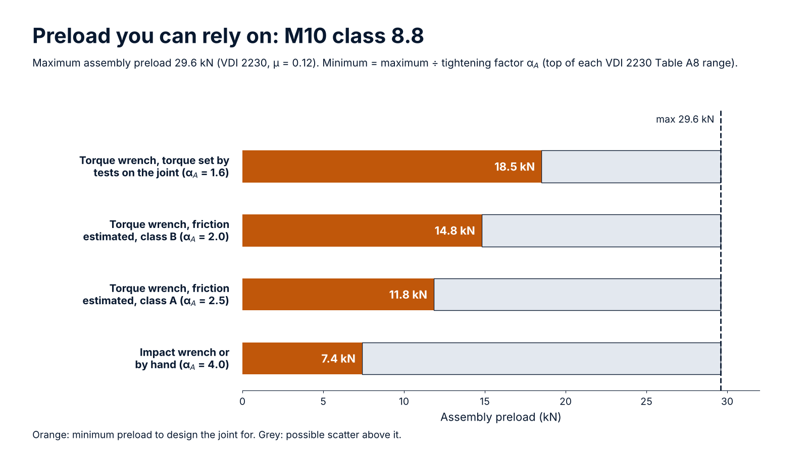
The bolt must survive the highest preload, but the joint must work with the lowest. For the M10 class 8.8 bolt above, with a maximum of 29.6 kN, the minimum you can rely on is 29.6 / 1.6 = 18.5 kN with a torque wrench whose torque was found by tests on the joint (αA = 1.6, the top of that range), and only 29.6 / 4.0 = 7.4 kN with an impact wrench (αA = 4.0). Design the joint (slip resistance, sealing, separation) for that minimum, and remember that some preload is also lost after tightening as the surfaces settle (embedding).
This FM,max / αA approach applies to every method in the table except yield-point and angle-controlled tightening. With yield-point or angle-controlled tightening the bolt is taken to its yield point, so VDI 2230 sizes the bolt differently; follow the guideline or the tool supplier for those methods. For simplicity the figure applies every tightening factor to the same 29.6 kN maximum; in a real calculation the maximum is taken at the lowest friction of the bolt's own friction class.
If a joint is critical, do not rely on torque alone. Angle-controlled tightening, yield-point control, direct tension indicators, ultrasonic measurement of bolt elongation or hydraulic tensioning all control preload better than torque control, and much better than a torque calculated from an estimated friction coefficient.
Common mistakes
- Using a torque chart without knowing its friction assumption. Always check which μ or K the chart was made for and match it to the actual finish and lubricant.
- Changing the coating or lubricant without changing the torque. A switch from plain to zinc-flake coated or waxed bolts, or adding anti-seize, can overload the bolt at the old torque.
- Lubricating only the thread or only the head. Both friction coefficients matter. Friction under the head takes almost half of the total torque.
- Ignoring the prevailing torque of self-locking nuts. With prevailing-torque nuts or screws (nylon insert or all-metal), part of the wrench torque only overcomes the locking element. Measure the prevailing torque and add it to the calculated tightening torque (VDI 2230 calls it the overbolting moment, MÜ).
- Reusing bolts tightened beyond yield. Bolts tightened by angle or yield-point control into the plastic range should not be reused unless the bolt supplier or your standard says they can be.
- Wrong tightening sequence. On a flange or a cover with many bolts, tightening one bolt fully at a time unloads its neighbours. Tighten in a crosswise pattern in two or three stages.
- Forgetting the clamped material. Soft materials such as aluminium or plastics can be crushed under the head at full preload. Check the surface pressure and use a hardened washer or a flange head where needed.
- Applying carbon-steel charts to stainless steel bolts. Stainless steel bolts (ISO 3506-1) have different strengths and higher, more variable friction, and they can gall. Use the supplier's values.
Quick checklist for a torque specification
- Choose the bolt size and property class from the loads.
- Decide the target preload and the minimum clamping force the joint needs.
- Choose the tightening method and its tightening factor αA, and check that FM,min = FM,max / αA is still enough after embedding.
- Calculate the torque for the actual friction (or K) of the bolt finish and lubricant.
- Write the torque, the friction condition (coating and lubricant), the sequence and the tool on the drawing or assembly instruction.
To try other sizes, friction coefficients and tightening methods, use the free bolt torque calculator on proxom.co.uk. It follows the VDI 2230 method for metric coarse, UNC and UNF bolts and shows the minimum preload for the tightening factor you choose. For the materials of the clamped parts, see our Mechanics of Materials article, and for the design of an assembly as a whole see DFM and DFA.
Further reading: R. G. Budynas and J. K. Nisbett, Shigley's Mechanical Engineering Design, McGraw-Hill (chapter 8); VDI 2230 Part 1, Systematic calculation of highly stressed bolted joints; ISO 898-1, Mechanical properties of fasteners made of carbon steel and alloy steel.
The values in this article are for guidance. Check critical joints with a full calculation and your fastener supplier's data. If you need a bolted joint designed or checked, ask us for a quote.
Frequently asked questions
How do I calculate bolt preload?
Multiply the bolt's proof load by a target factor: 0.75 for joints that will be taken apart, 0.90 for permanent joints (Shigley). For an M10 class 8.8 bolt that is 0.75 × 33.7 kN = 25.3 kN. VDI 2230 instead sets the preload so that the combined stress from tension and thread torsion reaches 90 % of the minimum yield strength, which gives 29.6 kN for the same bolt at friction 0.12.
What torque should I use for an M10 8.8 bolt?
With the VDI 2230 table values (friction 0.12, 90 % yield utilisation), 48 N·m for a preload of 29.6 kN. With Shigley's method (K = 0.20, 75 % of proof load), about 51 N·m for a preload of 25.3 kN. Use the value whose friction assumption matches your bolt's coating and lubricant; for the VDI value, that means the lowest friction you expect.
What is the nut factor K?
The coefficient in T = K·F·d that links torque, preload and nominal diameter. It includes thread and under-head friction and the thread geometry. Typical values are 0.30 for black-finish steel, 0.20 for zinc-plated or unknown condition and 0.18 for lubricated bolts.
What is the difference between proof load and yield strength?
Proof load is a test load set by ISO 898-1 that the bolt must carry without permanent elongation. It is a little below the load at the bolt's minimum yield strength: for class 8.8 up to M16 the proof stress is 580 MPa and the minimum yield strength 640 MPa.
Does lubricating a bolt change the torque?
Yes. Lubrication lowers friction, so the same torque gives a much higher preload. Reduce the torque to the value calculated for the lubricated condition, or the bolt can yield.
Should I use the same torque for 10.9 and 8.8 bolts?
No. In the VDI 2230 table a 10.9 bolt carries about 42 % to 47 % more preload than an 8.8 bolt of the same size, so its torque is higher. At the same friction, using the 8.8 torque on a 10.9 bolt does not overload the bolt, but it gives only the 8.8 preload: the joint will be under-clamped if it was designed for the 10.9 preload. The reverse is dangerous: the 10.9 torque on an 8.8 bolt will yield or break it.