When a flat blank is bent, the outside of the bend stretches and the inside is compressed. The flat length is therefore not simply the sum of the flange lengths. To cut a blank that bends into the right size, you need the bend allowance, the bend deduction and the K-factor. CAD systems calculate these for you, but only from the values you give them, and a wrong K-factor or a wrong angle gives a wrong flat pattern on every part.
This article explains each term and gives the formulas. It shows how to choose a K-factor (including the DIN 6935 formula) and how to measure your own. Worked examples follow, including a common angle mistake that produces scrap.
Quick answer: for a bend through angle θ with inside radius R in sheet of thickness T, the bend allowance is BA = θ × (π / 180) × (R + K × T). With flanges measured to the virtual sharp (the theoretical sharp outside corner where the extended outside surfaces meet), flat length = A + B − BD, where the bend deduction BD = 2 × (R + T) × tan(θ / 2) − BA. For 2 mm sheet, R = 2 mm, K = 0.325 and a 90° bend, BA = 4.16 mm and BD = 3.84 mm. The K-factor (K = t / T) is the position of the neutral axis as a fraction of the thickness, usually 0.3 to 0.5.
To check your own part, use the free sheet metal bend allowance calculator on proxom.co.uk.
The neutral axis and the K-factor
Somewhere inside the thickness of the sheet is a layer that is neither stretched nor compressed by bending. This is the neutral axis. Its length does not change, so the flat length of the bend is the length of the neutral axis around the bend.
In a flat sheet the neutral axis is in the middle of the thickness. During bending it moves towards the inside of the bend. The K-factor gives its position:
K = t / T
where t is the distance from the inside surface to the neutral axis and T is the sheet thickness. K = 0.5 means the neutral axis is still in the middle. For most press brake bending of metal sheet, K lies roughly between 0.3 and 0.5: lower for tight radii, closer to 0.5 for large radii. Very tight radii (inside radius well below the sheet thickness) can give values below 0.3.
The terms you need
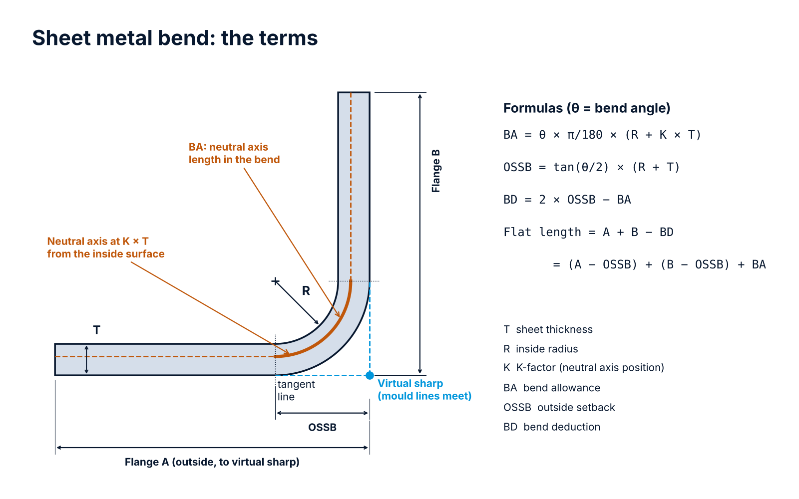
- Bend angle (θ): the angle through which the sheet is bent, measured from flat. An L-bracket has a 90° bend. A part whose flanges meet at an included angle of 135° has a bend angle of 45°.
- Inside radius (R): the radius on the inside of the bend.
- Bend allowance (BA): the length of the neutral axis through the bend, from one tangent line to the other.
- Mould line (mold line) and virtual sharp: extend the two outside surfaces of the flanges until they meet. That intersection is the virtual sharp (the outside apex), and the extended surfaces are the mould lines. Drawings usually dimension flanges to it.
- Outside setback (OSSB): the distance from the tangent line of the bend to the virtual sharp, measured along the mould line (the extended outside surface of the flange).
- Bend deduction (BD): the amount you subtract from the sum of the outside flange dimensions to get the flat length.
Bend allowance, bend deduction and setback formulas
With θ in degrees:
- Bend allowance: BA = θ × (π / 180) × (R + K × T)
- Outside setback: OSSB = tan(θ / 2) × (R + T)
- Bend deduction: BD = 2 × OSSB − BA
There are two ways to get the flat length. Used with the same flange dimensions, both give the same result:
- From outside dimensions (to the virtual sharp): L = A + B − BD
- From the straight lengths between bends: L = (A − OSSB) + (B − OSSB) + BA
For a 90° bend, tan 45° = 1, so OSSB = R + T and the formulas simplify to BA = 1.5708 × (R + K × T) and BD = 2 × (R + T) − BA.
The OSSB formula assumes that the flanges are dimensioned to the virtual sharp. That is practical for bends up to 90°. For bends of more than 90° (an included angle of less than 90°) the virtual sharp moves far away from the part, so drawings often dimension those flanges to a line that touches the outside of the bend and is perpendicular to the flange (the overall outside dimension, R + T beyond the tangent line). The deduction then becomes BD = 2 × (R + T) − BA, and in the second method you subtract R + T instead of OSSB from each flange. This is also how DIN 6935 treats included angles below 90°.
Worked example 1: an L-bracket
An L-bracket in 2 mm steel sheet, inside radius 2 mm, bent through 90°. The outside dimensions are 50 mm and 30 mm. With R / T = 1, the DIN 6935 formula below gives K = 0.325.
- BA = 1.5708 × (2 + 0.325 × 2) = 1.5708 × 2.65 = 4.163 mm
- OSSB = tan 45° × (2 + 2) = 4.000 mm
- BD = 2 × 4.000 − 4.163 = 3.837 mm
- Flat length L = 50 + 30 − 3.837 = 76.16 mm
Check with the second method: (50 − 4) + (30 − 4) + 4.163 = 46 + 26 + 4.163 = 76.16 mm.
You can reproduce this example in the free bend allowance calculator: enter thickness 2, inside radius 2, K-factor 0.325, angle 90°, A = 50 and B = 30. Its default K-factor is 0.40, which gives 76.40 mm instead.
Worked example 2: a U-channel
The same material and radius, a U-channel with outside dimensions 30 × 60 × 30 mm (two 90° bends). Subtract one bend deduction per bend:
L = 30 + 60 + 30 − 2 × 3.837 = 112.33 mm
Check: straight lengths between the tangent lines 26 + 52 + 26 mm, plus two bend allowances of 4.163 mm, gives 112.33 mm. The middle flange loses an outside setback at each end.
Worked example 3: the included-angle mistake
A bracket has flanges that meet at an included angle of 135°. The sheet is bent through 45°, not 135°. With the same material:
| Correct: θ = 45° | Wrong: θ = 135° | |
|---|---|---|
| Bend allowance | 2.081 mm | 6.244 mm |
| Outside setback | 1.657 mm | 9.657 mm |
| Bend deduction | 1.232 mm | 13.070 mm |
If the included angle is entered as the bend angle in the virtual-sharp formulas above (as most bend calculators use them), the bend deduction comes out 11.8 mm too large and the blank is cut about 11.8 mm too short. Some CAD systems and some fabricators' tables use the included angle and some use the bend angle (DIN 6935 itself writes its formulas with the included, or opening, angle), so always check which one a field or table expects.
How to choose a K-factor (K-factor chart)
The K-factor depends on the material, the ratio of inside radius to thickness, the bending method (air bending, bottoming or coining), the tooling and even the grain direction. There is no exact value you can look up for every case, but there are good starting points.
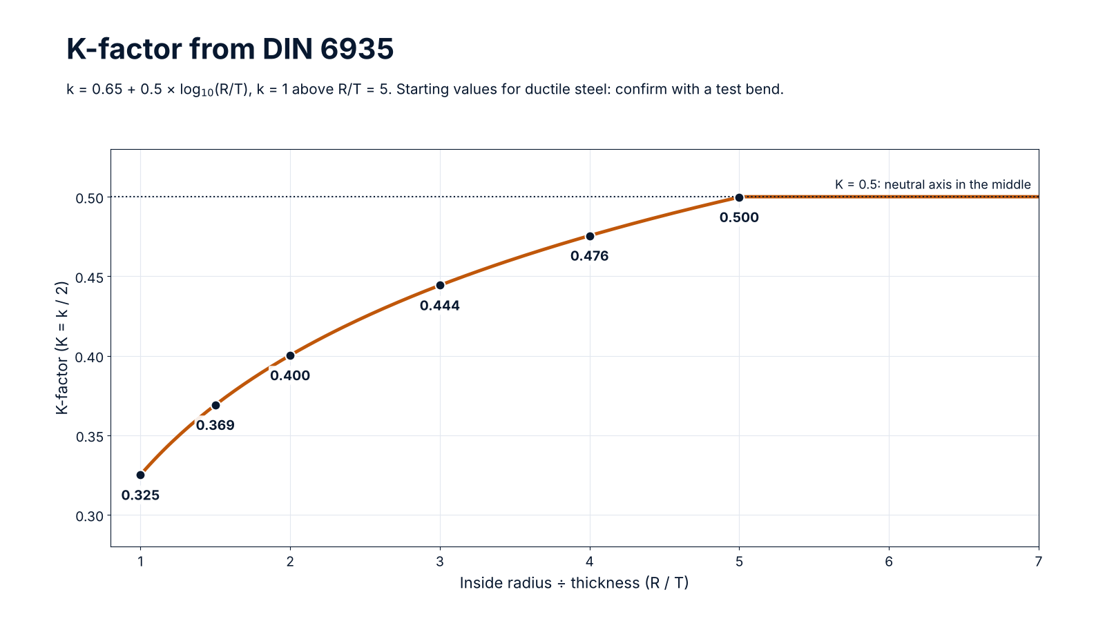
DIN 6935 (cold bending of flat steel products) gives a correction factor k from the ratio of inside radius to thickness:
k = 0.65 + 0.5 × log10(R / T), with k = 1 for R / T above 5
DIN's k describes the neutral axis position relative to half the thickness, so the K-factor used in most CAD systems is:
K = k / 2
| R / T | k (DIN 6935) | K = k / 2 |
|---|---|---|
| 1 | 0.650 | 0.325 |
| 1.5 | 0.738 | 0.369 |
| 2 | 0.801 | 0.400 |
| 3 | 0.889 | 0.444 |
| 4 | 0.951 | 0.476 |
| 5 | 0.999 | 0.500 |
| above 5 | 1 (fixed by DIN) | 0.500 |
The formula was developed for ductile steel. The values in this table come from the formula. DIN's own table of rounded k values starts at R / T = 0.65 and works in steps, reaching k = 1 already above about R / T = 3.8, so it can differ slightly from the formula. Below R / T = 0.65 the formula falls quickly (K = 0.25 at R / T = 0.5). For aluminium, stainless steel or high-strength steel the real K can be different, so treat these values as a starting point and confirm them with a test bend. Mixing up DIN's k and the CAD K-factor is a common error: entering 0.65 as a K-factor puts the neutral axis in the outer half of the sheet, which does not happen in press brake bending, and makes every flat pattern too long (by about 1 mm per 90° bend in 2 mm sheet with R = 2 mm).
Commonly published starting values for air bending. Many fabrication references give these generic K-factors by material hardness and radius:
| Material (air bending) | R from 0 to T | R from T to 3T | R over 3T |
|---|---|---|---|
| Soft (for example aluminium) | 0.33 | 0.40 | 0.50 |
| Medium (for example mild steel) | 0.38 | 0.43 | 0.50 |
| Hard (for example stainless steel) | 0.40 | 0.45 | 0.50 |
Sources differ on which materials belong in each column, so treat the material examples as indicative only. At small radii these values are higher than DIN 6935 gives; they are rules of thumb, not values from a standard. Use either table only as a starting point and confirm with a test bend; bottoming and coining give different values again.
Some CAD systems, such as PTC Creo, also use a Y-factor (in Creo it is the default bend allowance factor). It is the K-factor multiplied by π / 2: Y = K × π / 2. A K-factor of 0.325 is a Y-factor of 0.511.
How much does K matter? For a 90° bend, changing K by 0.1 changes the bend allowance by 0.1 × 1.5708 × T. In 2 mm sheet that is 0.31 mm per bend. On a part with four bends, a K-factor that is off by 0.1 moves the flat length by about 1.3 mm.
How to measure your own K-factor
The most accurate K-factor is one measured with the press brake, tooling and material you will use for production:
- Cut a strip of known flat length L, for example 100.00 mm, in the material and thickness you will use. Measure T.
- Bend it in the middle with the production tooling, as close to 90° as you can.
- Measure the actual bend angle θ with a protractor or angle gauge, the two outside flange dimensions A and B, and the inside radius R (radius gauges or an optical comparator work well). If the angle is not 90°, take the flange dimensions to the virtual sharp, not with a plain caliper across the outside.
- Calculate BD = A + B − L, then BA = 2 × OSSB − BD, then K = (BA / (θ × π / 180) − R) / T.
Example: T = 2.00 mm, R measured as 2.0 mm, L = 100.00 mm, both flanges measured at 51.95 mm. BD = 103.90 − 100.00 = 3.90 mm. OSSB = 4.00 mm, so BA = 8.00 − 3.90 = 4.10 mm. K = (4.10 / 1.5708 − 2.0) / 2.00 = 0.305.
Measure several strips and average them; an error of 0.05 mm in the sum of the two flange measurements changes K by about 0.016 in this example. The angle matters even more: a bend of 91° instead of 90° changes K by about 0.03, so always use the measured angle, not the nominal one. K and R also work as a pair: use the same R in your CAD model that you used to calculate K. Once you know the bend deduction your shop gets for a given material, thickness, radius and tooling, you can also enter it directly as a bend table in your CAD system instead of a K-factor.
Practical points
- Use the radius the press brake will actually make. In air bending the inside radius is set mainly by the die opening, not by the punch radius, as long as the punch radius is smaller than this natural radius (roughly 15 % to 17 % of the die opening for mild cold-rolled steel and 20 % to 22 % for 304 stainless steel, with a die opening suited to the thickness, typically 6 to 8 times T). A punch nose that is very sharp for the thickness (a common rule of thumb is below about 0.63 × T) creases the inside of the bend instead, and the radius no longer follows this rule. If the radius on the drawing is not the one the tooling produces, the flat pattern will be wrong even with the right K-factor. Ask your fabricator which radius their tooling gives for your material and thickness.
- Springback changes the angle, not the developed length. The press brake operator overbends to allow for springback. Calculate the flat length with the final angle and radius of the part.
- Say whether each flange is dimensioned to the outside (virtual sharp) or to the inside surface. Flat-length errors often come from a dimension that was drawn to the inside surface but read as an outside dimension.
- Add bend relief where a bend ends inside the sheet. Where a bend line stops before the edge of the part, a small relief cut stops the material tearing at the end of the bend.
- Very small bends. DIN 6935 sets the correction to zero for included angles above 165° (bends of less than 15°). The real deduction is not zero: in 2 mm sheet it is about 0.27 to 0.37 mm at a 15° bend and falls roughly in proportion to the angle (about 0.09 to 0.12 mm at 5°), so calculate it anyway when the tolerance is tight.
Sheet metal parts are also a good place to apply DFM and DFA principles: standard radii, a few common bend angles and consistent flange lengths reduce tooling changes and cost. If the flat length of a part feeds a tolerance stack-up, remember that each bend adds its own variation.
To check a bend quickly, use the free sheet metal bend allowance calculator on proxom.co.uk. It gives the bend allowance, bend deduction, outside setback and flat length from thickness, radius, K-factor and angle, in mm or inch. If you need sheet metal parts designed or flat patterns checked, ask us for a quote.
Frequently asked questions
What is the difference between bend allowance and bend deduction?
Bend allowance is the length of the neutral axis through the bend; you add it to the straight lengths between the bends. Bend deduction is what you subtract from the sum of the outside flange dimensions. Both give the same flat length when used with the matching dimensions.
What K-factor should I use for steel?
As a starting point, use the DIN 6935 formula value for your radius-to-thickness ratio: about 0.33 when the inside radius equals the thickness, 0.40 at twice the thickness and 0.50 at five times the thickness or more. Then confirm it with a test bend on your own tooling.
What is a K-factor of 0.5?
It means the neutral axis is in the middle of the sheet. That is the case for large bend radii (more than about five times the thickness by the DIN 6935 formula; DIN's rounded table already reaches 0.5 above about 3.8 times). For tight radii the neutral axis moves towards the inside, and K is lower.
Is the bend angle the same as the included angle?
No. The bend angle is how far the sheet is bent from flat; the included angle is the angle between the flanges of the finished part. They add up to 180°. A 90° bend is the only case where they are equal.
Why is my flat pattern wrong even though the formula is right?
Usually because the inside radius produced by the tooling differs from the radius in the model, the K-factor was not measured for the material and tooling used, or the bend angle and included angle were mixed up.